Recently, I had the chance to do the conceptual design of a steel pedestrian bridge (footbridge) project. One of the most interesting things I learned and had to deal with is the Pedestrian Load. Yes, it is the loading that comes from the weight of the people who will be using the bridge. It might sound trivial, but it could be critical in some cases.
Engineers started to be aware of the importance of this particular type of loading after the phenomenon that happened at London Millennium Bridge on 10 June 2000. This is a short video showing what happened on that day, which I found on YouTube.
The bridge was swaying due to the force from people’s movement! How come a crowd walking randomly could cause such huge impact on a bridge?
So, during the opening day, as thousands of people (estimated to be around 2,000 people were on top of the bridge at a given time) were walking on top the bridge, the loading from some of those people started to force the bridge to sway slightly. And then, as the bridge started to sway, some more people will be forced to balance themselves, and thus, created an even larger force that pushed the bridge even more (‘positive feedback’). The cycle repeated and created a synchronised movement, as seen in the video. In conclusion, the bridge and the pedestrians are resonating with each other!
Clearly, the bridge was strong enough to carry the load from all the people. However, the excessive sway would make it unusable. Therefore, putting proper attention into Pedestrian Load during the design stage of a bridge is important.
In this post I will share what I have learned about designing a bridge against Pedestrian Load. In general, there are two types of loading, i.e., Static Loading and Dynamic Loading.
A. STATIC LOADING
A.1 Loading Criteria
A.1 Loading Criteria
1. AASHTO LRFD Guide Specifications for the Design of Pedestrian Bridge (2009)
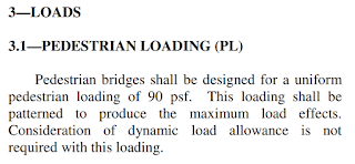
Referring to section 3.1, the static loading to be applied is 90 psf (≈ 4.3 kPa), which under ultimate condition can go up to 1.75 x 90 = 158 psf (≈ 7.56 kPa). Pattern loading to generate worst case scenario is also required.

AASHTO LRFD Guide Specifications for the Design of Pedestrian Bridge (2009) – Section 3.1
2. BS EN 1991-2:2003
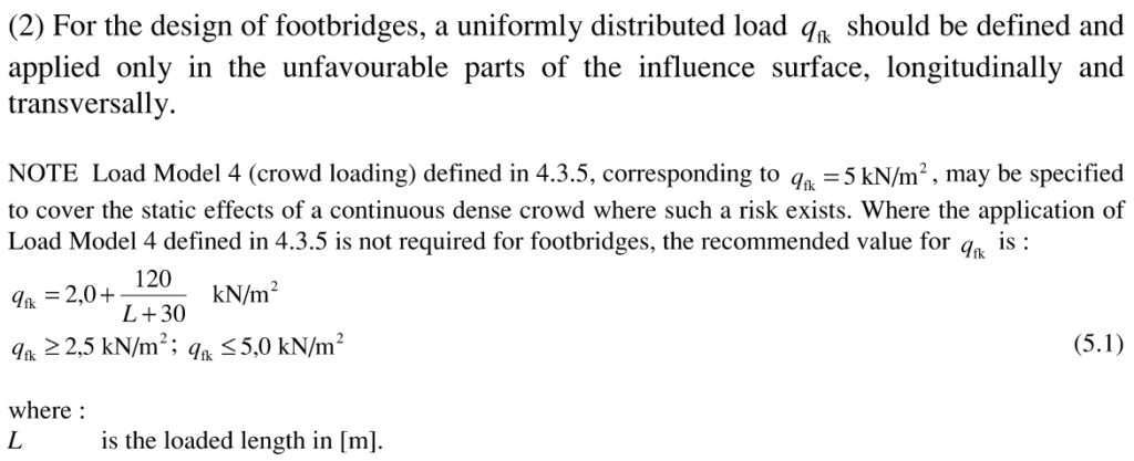
British Standard/Eurocode gives a more comprehensive approach. On top of it requiring the load to be applied at unfavourable parts (pattern loading) to achieve the worst case, it also considers the level of crowd loading that might happen. For example, if the bridge is located in a remote area with very little people on it at one time, the loading can be reduced. The allowed range for the live load is 2.5kPa ≤ qfk ≤ 5.0kPa.

BS EN 1991-2:2003 – Section 5.3.2.1 (2)
Upon reading the next section in the code, you will find that Eurocode also requires checking against 10kN point load acting on a square surface of sides 0.1m to take into account any local effects.
And lastly, in section 5.3.2.3, static horizontal force is also required by the code, acting along the bridge deck pavement level. It is taken as equal to the greater of (1) 10% of total uniformly distributed vertical load and (2) 60% of the total weight of service vehicle.
A.2 Verification Process
The verification for static behaviour is pretty straightforward. Similar to other loads, the bridge will be checked against its strength and serviceability (deflection) under the specified loads.
B. DYNAMIC Loading
Checks on the dynamic side of the structure is essential for a very obvious reason. The sway movement on London Bridge was a result of the Dynamic Behaviour of the bridge. Therefore, it is necessary to ensure the bridge we design would not fall into the same mistake.
Since we are dealing with quite random dynamic loading (walking, running, jumping, standing, cycling, etc), you will see that the requirements are not related to loading in a certain magnitude, but rather, to numbers that would represent the dynamic properties of the bridge.
1. Bridge Deck Natural Frequency
Natural frequency of a structure is the frequency at which the structure would oscillate when there is no external forces. If an external dynamic force having the same frequency as the structure’s natural frequency is applied to the structure, the structure would resonate and the response of the structure would increase significantly (as what happened to London Millennium Bridge). See the following illustration to understand how a system is affected by harmonic loading.

Acceleration Response Factor for Damped Systems Excited by Harmonic Loading (Chopra, 1995)
Note that, theoretically, without damping, a resonating structure under harmonic load would have its response multiplied to infinity!
In our case, therefore, we want our bridge to be such that its natural frequency is not close to human footstep frequency. There are three types of vibrations to be checked: Vertical, Horizontal, and Torsional Vibrations. Eurocode BS EN 1990 clause A2.4.3.2(2) sets 0~2.5Hz as the critical zone for Lateral and Torsional Vibrations, and 0~5.0Hz for Vertical Vibration.
2. Maximum Acceleration – Dynamic Loading Analysis
There are some cases where your bridge might fall into the limit zone, or the ‘critical zone’. However, this is not the end of the world. In this situation, we would need refer to the other comfortability criteria, which is the Maximum Acceleration. Basically, we apply harmonic vertical load on the bridge deck considering vertical walking paths offset from the bridge (as necessary) and we assess the Maximum Acceleration. According to the graph above, if the structure has enough damping, the resonance effect will be diminished to an acceptable value. BS EN 1990 clause A2.4.3.2(1) sets 0.2m/s^2 as the maximum acceptable acceleration value.
3. Dampers and Structural System Modifications
Dampers can be used to introduce bigger damping into structure. In case the acceleration value exceeds the limit, the use of damper might be able to rectify this situation. One example is Viscous Damper, which is used in London Millennium Bridge. Other types of bearing used in footbridges are Tuned Mass Damper, and, upon research, I found out there is another damper called Liquid Column Damper.
Structural modifications can also be another alternative. Adding/reducing mass, braces, modifying support locations, etc, would change the structure dynamic behaviour and sometimes can be the most economical solution.